I am trying to use tensorflow-lite on a esp32_cam to classify images. I defined the following sub-tasks that i need to solve:
- Take photo
- Reduce size of photo to (e.g.) 28x28 pixels grayscale
- run inference with trained model
For now I am stuck between point 1 and 2 and cannot get it solved.
What i have done so far:
I save an image into buffer using esp_camera_fb_get(). Afterwards I put the values from the buffer inside a 2D array.
However, when I print out some of these values, they never become 0 nor 255, even though I coverd the whole lens or put a bright light source close to it.
I have four questions:
- How do i correctly record an image?
- How can I convert it into a 2D array?
- How can I downsample the size from (e.g.) 160x120 to 28x28?
- how can I correctly
Serial.print()each pixel value to copy the values and plot them on my computer (e.g. with python matplotlib)
#define CAMERA_MODEL_AI_THINKER
 #include <esp_camera.h>
 #include "camera_pins.h"

 #define FRAME_SIZE FRAMESIZE_QQVGA
 #define WIDTH 160
 #define HEIGHT 120

 uint16_t img_array [HEIGHT][WIDTH] = { 0 };


 bool setup_camera(framesize_t);
 void frame_to_array(camera_fb_t * frame);
 void print_image_shape(camera_fb_t * frame);
 bool capture_image();

 void setup() {
     Serial.begin(115200);
     Serial.println(setup_camera(FRAME_SIZE) ? "OK" : "ERR INIT");
 }

 void loop() {
     if (!capture_image()) {
         Serial.println("Failed capture");
         delay(2000);

         return;
     }

     //print_features();
     delay(3000);
 }


 bool setup_camera(framesize_t frameSize) {
     camera_config_t config;

     config.ledc_channel = LEDC_CHANNEL_0;
     config.ledc_timer = LEDC_TIMER_0;
     config.pin_d0 = Y2_GPIO_NUM;
     config.pin_d1 = Y3_GPIO_NUM;
     config.pin_d2 = Y4_GPIO_NUM;
     config.pin_d3 = Y5_GPIO_NUM;
     config.pin_d4 = Y6_GPIO_NUM;
     config.pin_d5 = Y7_GPIO_NUM;
     config.pin_d6 = Y8_GPIO_NUM;
     config.pin_d7 = Y9_GPIO_NUM;
     config.pin_xclk = XCLK_GPIO_NUM;
     config.pin_pclk = PCLK_GPIO_NUM;
     config.pin_vsync = VSYNC_GPIO_NUM;
     config.pin_href = HREF_GPIO_NUM;
     config.pin_sscb_sda = SIOD_GPIO_NUM;
     config.pin_sscb_scl = SIOC_GPIO_NUM;
     config.pin_pwdn = PWDN_GPIO_NUM;
     config.pin_reset = RESET_GPIO_NUM;
     config.xclk_freq_hz = 20000000;
     config.pixel_format = PIXFORMAT_GRAYSCALE;
     config.frame_size = frameSize;
     config.jpeg_quality = 12;
     config.fb_count = 1;

     bool ok = esp_camera_init(&config) == ESP_OK;

     sensor_t *sensor = esp_camera_sensor_get();
     sensor->set_framesize(sensor, frameSize);

     return ok;
 }


 bool capture_image() {

     camera_fb_t * frame = NULL;
     frame = esp_camera_fb_get();

     print_image_shape(frame);

     frame_to_array(frame);

     esp_camera_fb_return(frame);

     if (!frame)
         return false;

     return true;
 }


 void print_image_shape(camera_fb_t * frame){

     // print shape of image and total length (=heigth*width)
     Serial.print("Width: ");
     Serial.print(frame->width);
     Serial.print("\tHeigth: ");
     Serial.print(frame->height);
     Serial.print("\tLength: ");
     Serial.println(frame->len);
 }

 void frame_to_array(camera_fb_t * frame){

     int len = frame->len;
     char imgBuffer[frame->len];
     int counter = 0;

     uint16_t img_array [HEIGHT][WIDTH] = { 0 };

     int h_counter = 0;
     int w_counter = 0;

     // write values from buffer into 2D Array
     for (int h=0; h < HEIGHT; h++){
         //Serial.println(h);
         for (int w=0; w < WIDTH; w++){
             //Serial.println(w);
             int position = h*(len/HEIGHT)+w;

             //Serial.println(position);
             img_array[h][w] = {frame->buf[position]};

             //Serial.print(img_array[h][w]);
             //Serial.print(",");
             //delay(2);
         }
     }


     //Serial.println("Current frame:");

     Serial.println("=====================");

 }
camera_pin.h:
#if defined(CAMERA_MODEL_WROVER_KIT)
#define PWDN_GPIO_NUM    -1
#define RESET_GPIO_NUM   -1
#define XCLK_GPIO_NUM    21
#define SIOD_GPIO_NUM    26
#define SIOC_GPIO_NUM    27

#define Y9_GPIO_NUM      35
#define Y8_GPIO_NUM      34
#define Y7_GPIO_NUM      39
#define Y6_GPIO_NUM      36
#define Y5_GPIO_NUM      19
#define Y4_GPIO_NUM      18
#define Y3_GPIO_NUM       5
#define Y2_GPIO_NUM       4
#define VSYNC_GPIO_NUM   25
#define HREF_GPIO_NUM    23
#define PCLK_GPIO_NUM    22

#elif defined(CAMERA_MODEL_ESP_EYE)
#define PWDN_GPIO_NUM    -1
#define RESET_GPIO_NUM   -1
#define XCLK_GPIO_NUM    4
#define SIOD_GPIO_NUM    18
#define SIOC_GPIO_NUM    23

#define Y9_GPIO_NUM      36
#define Y8_GPIO_NUM      37
#define Y7_GPIO_NUM      38
#define Y6_GPIO_NUM      39
#define Y5_GPIO_NUM      35
#define Y4_GPIO_NUM      14
#define Y3_GPIO_NUM      13
#define Y2_GPIO_NUM      34
#define VSYNC_GPIO_NUM   5
#define HREF_GPIO_NUM    27
#define PCLK_GPIO_NUM    25

#elif defined(CAMERA_MODEL_M5STACK_PSRAM)
#define PWDN_GPIO_NUM     -1
#define RESET_GPIO_NUM    15
#define XCLK_GPIO_NUM     27
#define SIOD_GPIO_NUM     25
#define SIOC_GPIO_NUM     23

#define Y9_GPIO_NUM       19
#define Y8_GPIO_NUM       36
#define Y7_GPIO_NUM       18
#define Y6_GPIO_NUM       39
#define Y5_GPIO_NUM        5
#define Y4_GPIO_NUM       34
#define Y3_GPIO_NUM       35
#define Y2_GPIO_NUM       32
#define VSYNC_GPIO_NUM    22
#define HREF_GPIO_NUM     26
#define PCLK_GPIO_NUM     21

#elif defined(CAMERA_MODEL_M5STACK_WIDE)
#define PWDN_GPIO_NUM     -1
#define RESET_GPIO_NUM    15
#define XCLK_GPIO_NUM     27
#define SIOD_GPIO_NUM     22
#define SIOC_GPIO_NUM     23

#define Y9_GPIO_NUM       19
#define Y8_GPIO_NUM       36
#define Y7_GPIO_NUM       18
#define Y6_GPIO_NUM       39
#define Y5_GPIO_NUM        5
#define Y4_GPIO_NUM       34
#define Y3_GPIO_NUM       35
#define Y2_GPIO_NUM       32
#define VSYNC_GPIO_NUM    25
#define HREF_GPIO_NUM     26
#define PCLK_GPIO_NUM     21

#elif defined(CAMERA_MODEL_AI_THINKER)
#define PWDN_GPIO_NUM     32
#define RESET_GPIO_NUM    -1
#define XCLK_GPIO_NUM      0
#define SIOD_GPIO_NUM     26
#define SIOC_GPIO_NUM     27

#define Y9_GPIO_NUM       35
#define Y8_GPIO_NUM       34
#define Y7_GPIO_NUM       39
#define Y6_GPIO_NUM       36
#define Y5_GPIO_NUM       21
#define Y4_GPIO_NUM       19
#define Y3_GPIO_NUM       18
#define Y2_GPIO_NUM        5
#define VSYNC_GPIO_NUM    25
#define HREF_GPIO_NUM     23
#define PCLK_GPIO_NUM     22

#else
#error "Camera model not selected"
#endif

I haven't worked with the ESP32 Camera so I can't talk about that but I've done a similar project on STM32 so here is all I can answer:
1. How do I correctly record an image?
I also had trouble setting up a camera on my microcontroller so I thought the same as you, getting back the image to the PC through serial. Please refer to point 4.
2. How can I convert it into a 2D array?
I suspect you want to do this for copying it to the tflite micro model input buffer. If that's the case, you don't need to! You can write your flattened 1D image array to the model input buffer because that's what tflite micro actually expects:
EDIT: The last line takes the
model_inputpointer to the model input structure and accesses itsdatamember(see this if you are not familiar with struct pointers in C). Then, since I assumed your model input data type is 8 bit signed integers, it accesses the data union withint8. If your model input data type were 32-bit floats you could have usedmodel_input->data.f[i]for example. Here is the source code with all available access types. After correctly addressing the model input buffer, we assign the correspondingimg_arraypixel data. Since the pixel data ranges from [0, 255], we need to convert it to a valid signed 8-bit integer type and range, so you must subtract 128, resulting in a [-128, 127] range.Hopefully, you get the idea. Let me know if you are using other formats like RGB565 and I'll give you a different snippet.
EDIT: If you are capturing RGB images, the most used format is RGB565, meaning there is a pixel data every 16 bits(5 for red, 6 for green, 5 for blue). Here is a snippet that transforms an image captured in that format to RGB888(which is what your model will probably expect) and copies it to the model input buffer:
Here is a step by step guide on RGB888 to RGB565 in C, I just did the inverse of that. You may have noticed the multiplications after masking out the color channel bits. Take red for example: once you mask out the bits
(color & 0xF800) >> 11)the red value will go from [0, (2^5)-1] but we want a [0, 255] range, so we divide by that number( (2^5)-1 = 31 = 0x1F ) and multiply by 255, giving the range we wanted. We can then subtract 128 to get a [-128, 127] signed 8-bit range. The fact that multiplication is done before is to keep precision. The blue channel is the same and in the green one, we divide by (2^6)-1=63=0x3F because it has 6 bits.3. How can I downsample the size from (e.g.) 160x120 to 28x28?
You could implement an algorithm in C but I took the easy way: I added a preprocessing lambda layer in my already trained model that did just that:
EDIT: Most computer vision models expect the image input value range to be [0, 1] or [-1, 1] but pixel values are usually 8-bit, so their range is [0, 255]. To normalize their values to a desired range [a, b], we can apply the following formula:
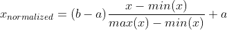
In our case, min(x)=0, max(x)=255, a=-1, b=1. Therefore, each normalized value is x_normalized = x_value/127.5 -1.
Intuitively you can see how 255/127.5 -1 = 1, and how 0/255 -1 = -1. That is where the 127.5 and -1 values come from.
Now you can define your complete model:
This way, the final model had an input shape equal to the camera capture resolution. This allowed me to copy the image array as shown in point 2.
4. How can I correctly Serial.print() each pixel value to copy the values and plot them on my computer (e.g. with python matplotlib)
I tried a couple of things and this is what worked for me: You can try printing the values like this
123, 32, 1, 78, 90,(i.e. separated by commas) which should be fairly easy to do. Then, if you are using Arduino you can use this cool program to log the serial data. If you are not using arduino, Putty has logging features. Then you can do something like this:The process of capturing an image and saving the log is a bit cumbersome but it shouldn't be too frustrating as this is only to debug if your image was captured correctly.
This is a very general question so let me know if I missed something or you want more depth on some aspects.
Edit
I've made public(and open source) my full code and documentation on this repository which contains a very similar app to what you are building. Furthermore, I'm also planning on porting the computer vision example to ESP32. Please note the repository is under development and will be for a while, although this example is already finished(pending revision).
I think a lot of people interested in deep learning on microcontrollers will find the repository interesting and useful.