Raspberry pi 2 and BMP280 : Slave address was not acknowledged

2.9k Views Asked by At

I follow the project WheatherStation on https://www.hackster.io Windows IOT.
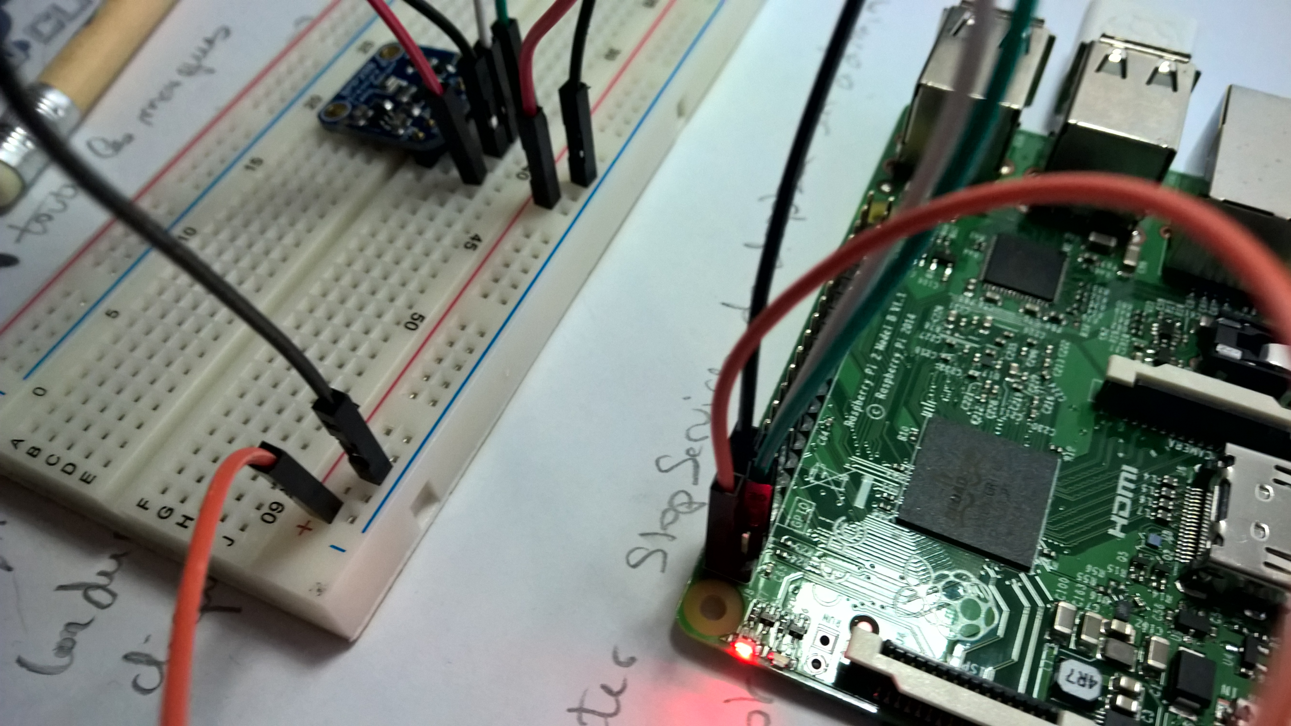
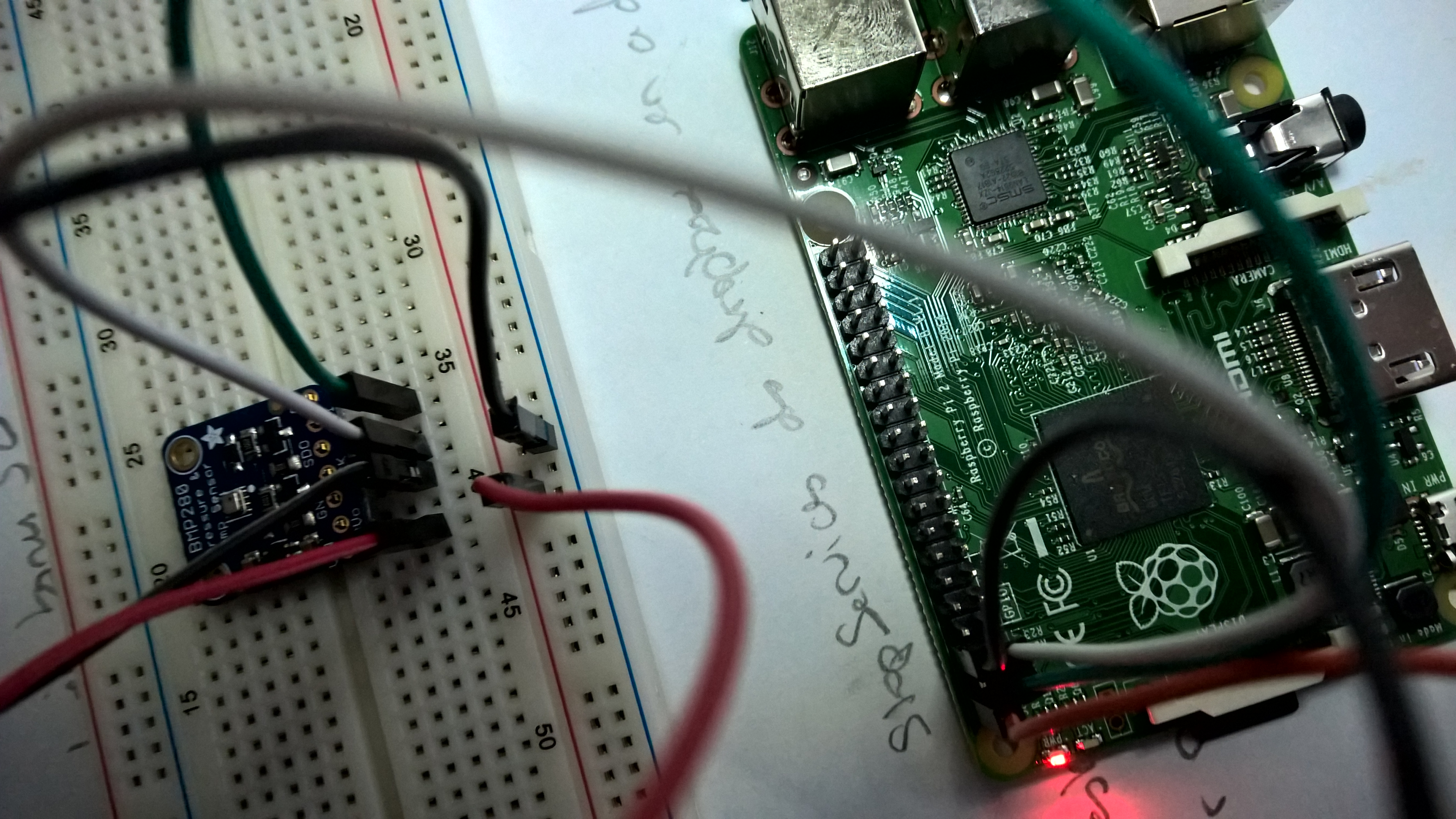
I downloaded project on github and connected my BMP280 sensor on Raspberry.
You can check my connections on

For me, it's correct, but i have an exception with bmp280.WriteRead(WriteBuffer, ReadBuffer);

System.IO.FileNotFoundException: The system cannot find the file specified. Slave address was not acknowledged.

4

There are 4 best solutions below

0
On BEST ANSWER

You had to solder the BMP280...

0
On

This may be an issue with I2C bus (since ACK is not received).

If that is fine, cross-check if you have cloned their repo using the --recursive flag? All sub-modules would be properly cloned using this. (There may be some file missing otherwise.)

0
On

Check your wires. Make sure they are completely pushed and at the right place. It was the problem for me.

0
On

There are a couple of different causes for this issue, most of which relate to hardware.

I see you're using the Adafruit breakout board and will reference the pins based on this.

  1. Make sure your SDO and SCL lines are properly connected to your Raspberry PI. SDO should connect to Pin 3 and SCL should connect to pin 5. From looking at your diagram pictures this should be correct.

  2. Next up is Vin. The Fritzing Image is incorrect on the Hackster.io. Vin should be connected to your 3.3V line, Pin 1 on your PI.

    This is because Vin is the supply level of your logic signal. In this case the Raspberry PI is 3.3V, putting it at 5 can cause issues where data is not properly clocked in via I2C.

  3. Lastly, pull SDO high by tying it to V3.3.

    The reason for this is if you read the datasheet for the BMP280/BME280 and look at the schematic you will see SDO has a pullup resistor that pulls it to 3.3V it's internal logic level. This is going to be exceptionally weird if using 5v rails as you're not technically in a tristate neither low nor hi so you will probably end up with a random address.

    Pulling this to 0V via ground will cause the slave address to be 0x76. With it pulled high the slave address of the BMP280/BME280 sensor will be 0x77. From looking at their supplied code they expect this pin to be pulled high giving a 0x77 address.

An alternative software solution for #3 is to change the I2C Slave address in the BME280 device code. In the example code this is contained within Lesson_203\StartSolution\BMP280.cs:

class BMP280
{
    //The BMP280 register addresses according the the datasheet: http://www.adafruit.com/datasheets/BST-BMP280-DS001-11.pdf
    const byte BMP280_Address = 0x77;  //If SDI is pulled high 0x77, if pulled low 0x76
    const byte BMP280_Signature = 0x58;

Lastly, your pin connections on your Pi if you're looking at the pi from the top with the HDMI port pointing towards you and the SD card slot on the left you are interested in the left most pins of the 40 pin header.

5V | 5V | Ground
3.3V | SDA(SDI) | SCLK

See also this header map. Pi3 Header Map